
High-Speed PCB Layout Engineering: 50Ω Controlled Impedance, Return Paths, Stackup & EMC Compliance
Practical hardware guide covering high-speed transmission lines, microstrip and stripline formulas, return path discontinuities across split ground planes, decoupling capacitor placement, and EMI/EMC compliance techniques.

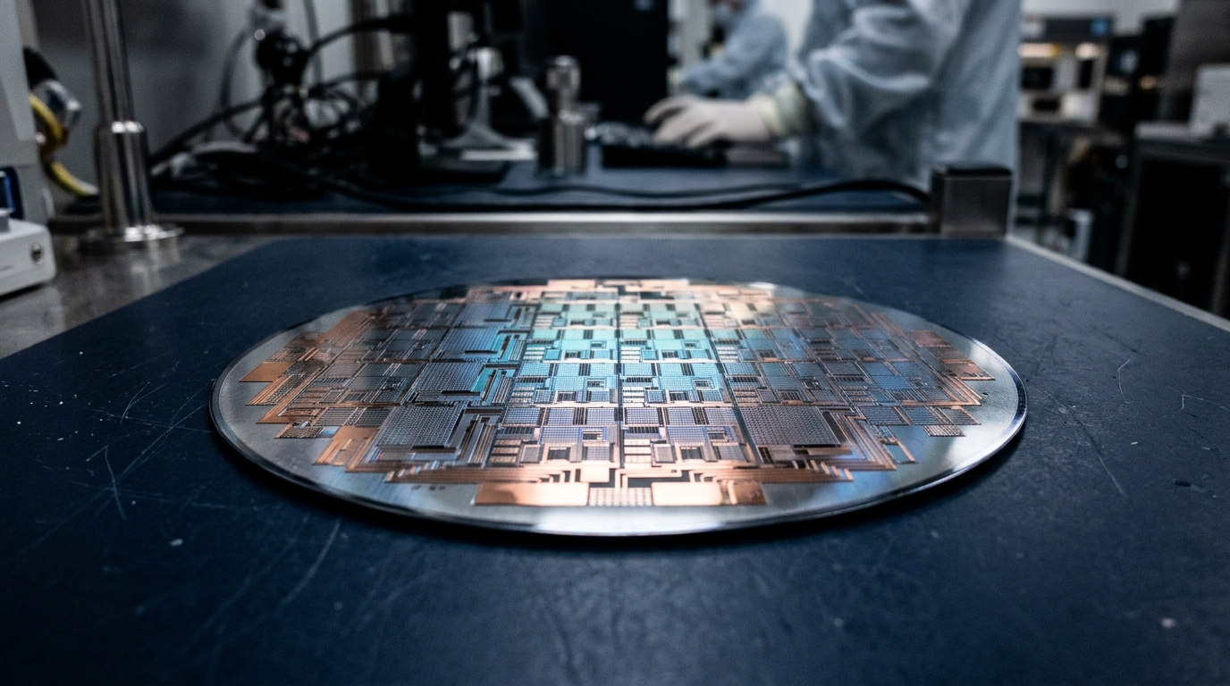
High-Speed PCB Layout Engineering: 50Ω Controlled Impedance, Return Paths, Stackup & EMC Compliance
As digital signals transition in sub-nanosecond rise times, printed circuit board traces cease to behave as simple lumped conductors and must be designed as distributed transmission lines. Poor PCB routing leads to signal ringing, timing skew, ground bounce, and radiated emissions failures.
1. When Does a PCB Trace Become a Transmission Line?
A trace must be treated as a transmission line when its electrical length exceeds one-sixth of the signal rise-time distance:
Length_critical >= (t_rise / 6) * v_propagation
In standard FR4 substrate, signals travel at roughly 6 inches per nanosecond (15 cm/ns). If an MCU SPI or USB edge rate is t_rise = 1 ns, any trace longer than 1 inch (2.5 cm) requires controlled impedance termination.
2. 50-Ohm Microstrip Characteristic Impedance (Z0)
For a surface microstrip trace of width w and copper thickness t separated by dielectric height h with dielectric constant eps_r:
Z0 ≈ [ 87 / sqrt(eps_r + 1.41) ] * ln[ (5.98 * h) / (0.8 * w + t) ]
For 1.6mm 4-layer standard stackup (Signal - GND - Power - Signal with h ≈ 0.2mm prepreg), a 50-ohm trace width is typically 12 to 14 mils (0.3mm to 0.35mm).
3. Return Path Continuity: The #1 EMC Rule
High-frequency return current does NOT follow the path of least resistance (DC); it follows the path of lowest loop inductance, directly beneath the signal trace on the adjacent reference plane.
Never route high-speed signals (clocks, USB, DDR, QSPI) across splits or voids in ground planes.
Technical Discussion (0)
Sign in with your EIHOUSE INDIA account to join the technical discussion.
Sign In to CommentNo comments yet. Be the first engineer to contribute to this discussion.